
- Product Name
- Product Keyword
- Product Model
- Product Summary
- Product Description
- Multi Field Search
Views: 19 Author: Site Editor Publish Time: 2020-03-10 Origin: Site
1. Software operation
1. Run NovaLCT
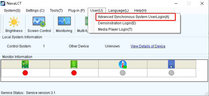
Figure 1
2. Login as Advanced user, and the password is “admin”
Figure 2
3. Click 【Screen Configuration】 Icon, select 【Configuration Screen】, then click 【Next】, like shown in Figure 3.
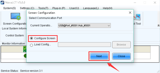
Figure 3
4. Enter the【Screen Connection】page, then click 【Configur】
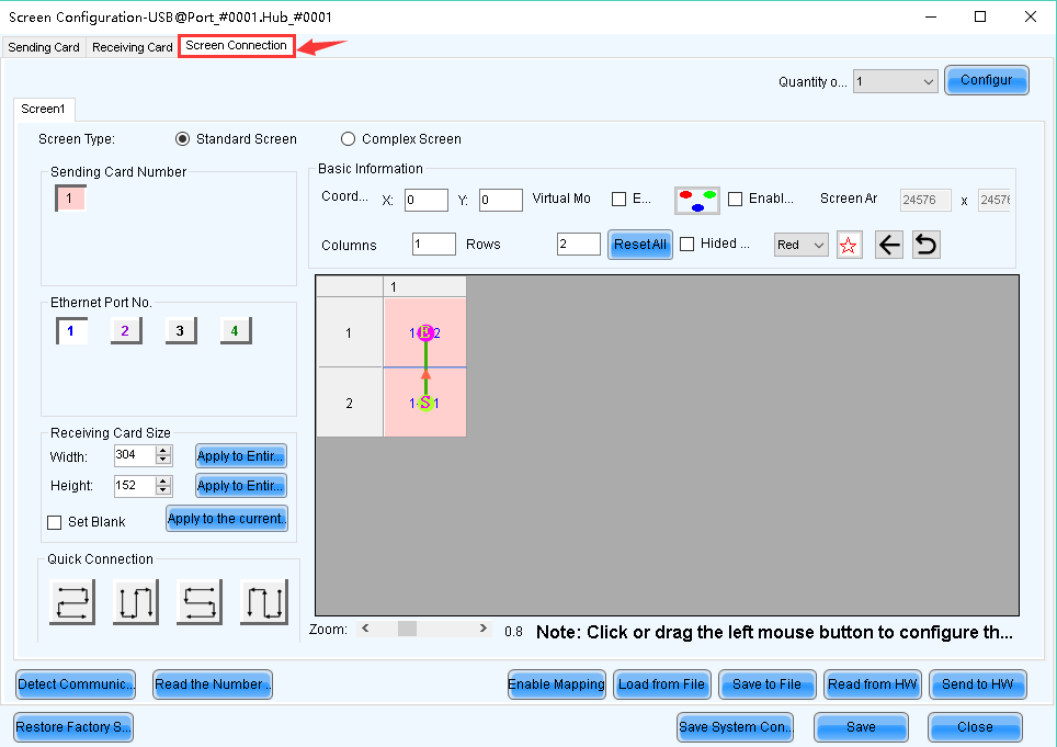
Figure 4
4.1 Select 【Standard Screen】, set how many Scan Boards (Receiving cards) are used in Column and Row, how many pixels one Scan Board (Receiving card) manages in Width and Height, and connect Scan Boards (Receiving cards) based on fact.
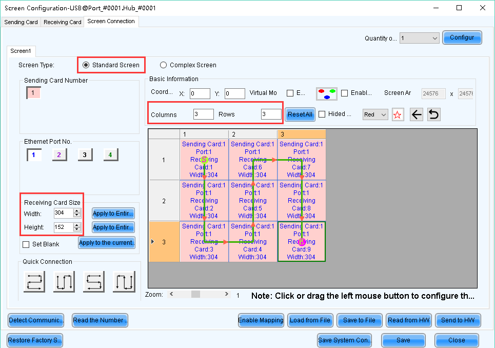
Figure 5
Note:
1. If the pixel quantity managed by one receiving card in Width and Height wasn’t set correctly, just correct it, and then click “Apply to port” to change it.
2. Select corresponding “Port Index” when conduct Scan Board (Receiving card) connection. Configure Scan Board (Receiving card) connection pattern for each port individually if more than one port is used.
3. The Scan Board (Receiving card) connection pattern must be the same for each LED display if one Ethernet cable is used to connect multiple LED displays.
For example, one Ethernet cable is used to connect two LED displays, input 2 at 【Screen number】, then click 【Config】. Both Screens need to be configured in the 【Screen Config】 page, the Scan Board connection pattern must be the same for both of them. Same programs will be shown on them if their Location (x, y)=(0,0). Different programs can be shown by changing one screen’s Location (x, y). (Total pixels of the two screens should be less than the sending card capacity and the Graphic card maximum resolution.)
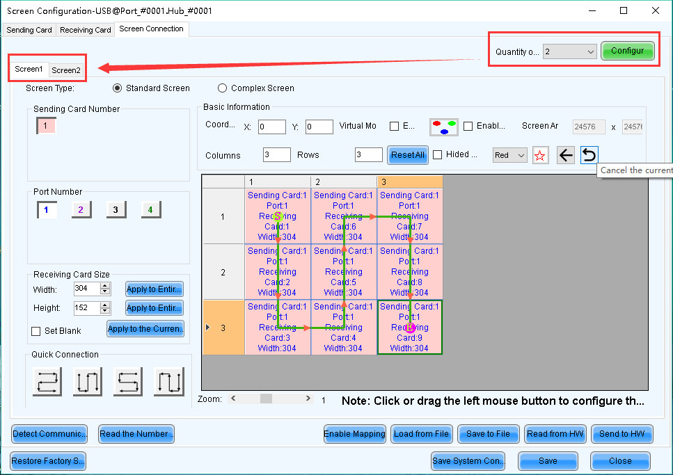
Figure 6

Figure 7 Set the Virtual mode
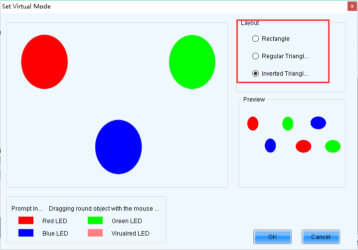
Figure8 Select layout of LED
Note:
If some Scan Boards (Receiving cards) manage different quantity of pixels from others, specific Scan Board (Receiving card) Size in Width and Height can be set individually.
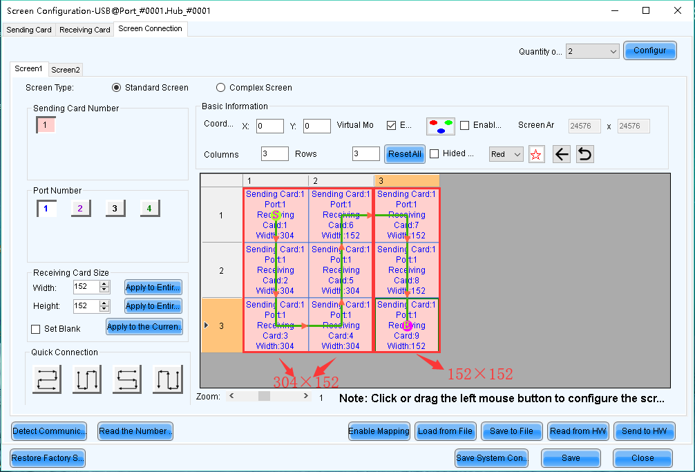
Figure 9 304×152 & 152×152
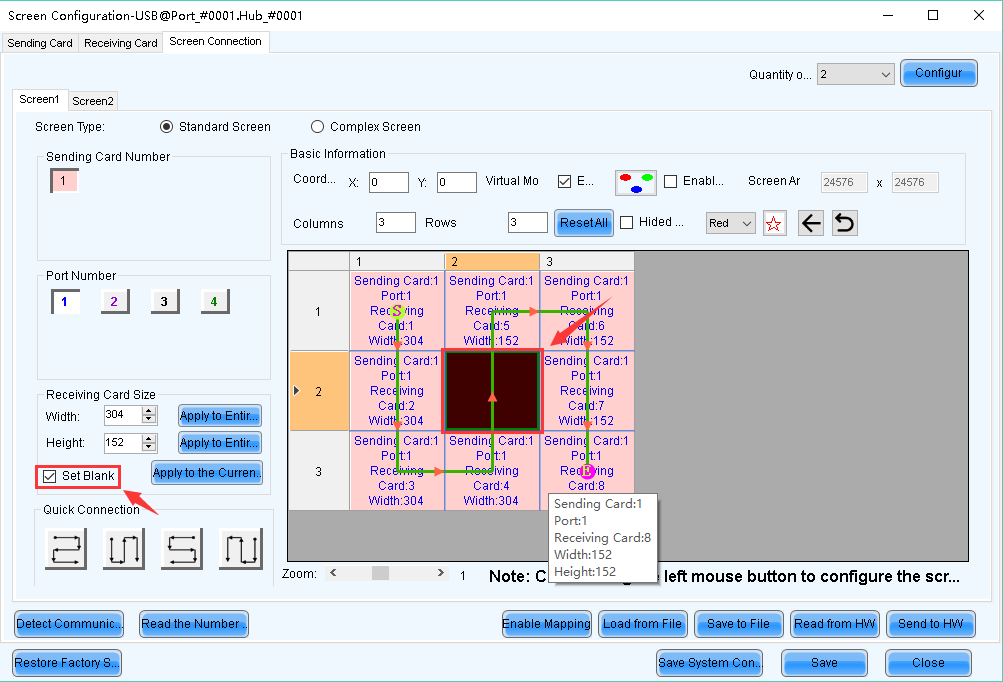
Figure 10 Blank set if there no cabinets on screen
4.2
Select 【Complex Screen】, set corresponding sending card, port, pixels managed by each receiving card and origin coordinates (x,y).
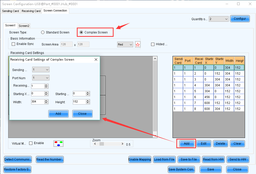
Figure 11
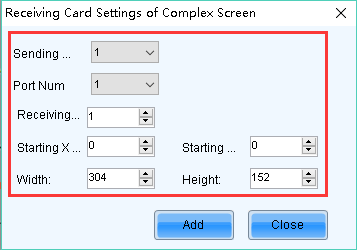
Figure 12
5. Click 【Send to HW】and 【Save】 when finishing the settings.
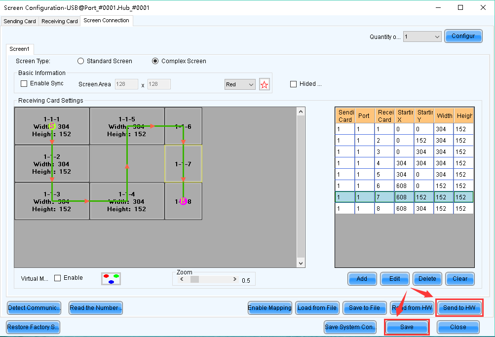
Figure 13


